CLEVELAND SELECTION
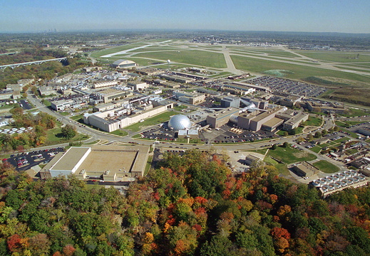
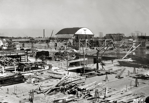
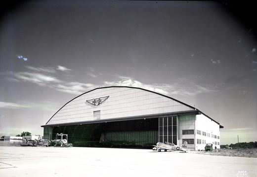
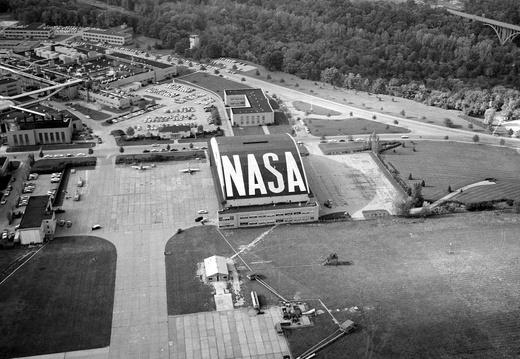
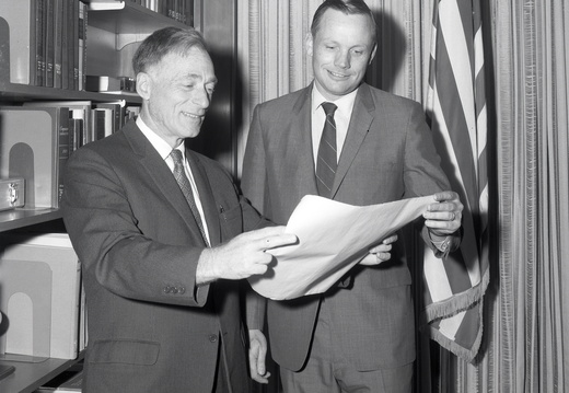
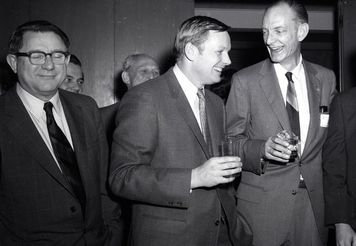
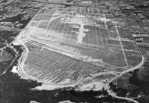
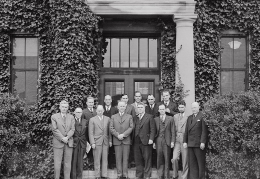
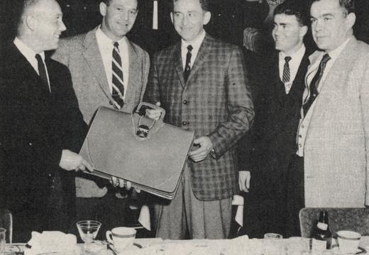
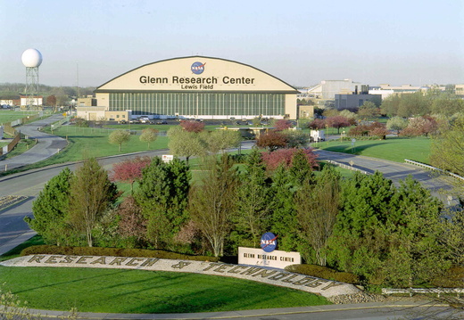
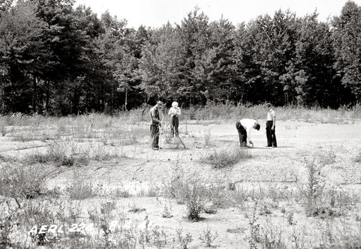
In 1940, the NACA sought a location for its new engine research laboratory (today NASA Glenn Research Center). Cleveland, Ohio’s aviation industry and renowned airport made it a leading contender for the site, but it was the steadfast effort of a small cadre of local officials that secured the agreement. The endeavor has generated over 75 years of technical and economic impact for Cleveland.
1×1 SUPERSONIC WIND TUNNEL
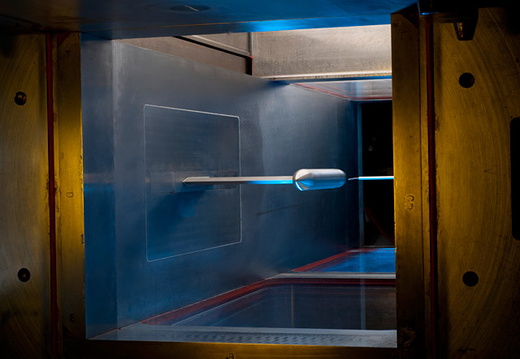
The 1×1 is a facility located in the Engine Research Building (ERB) at NASA’s Glenn Research Center in Cleveland, Ohio. This facility is used to conduct fundamental research in supersonic and hypersonic fluid mechanics, supersonic-vehicle-focused research and detailed benchmark quality experiments for CFD code validation.
The tunnel can provide continuous operation at 10 discrete airspeeds from Mach 1.3 to 6.0 by using an appropriate fixed-area contoured nozzle block upstream of the test section.
A number of specialized support systems are available to meet the research customer’s needs such as auxiliary bleed, model hydraulics, and probe actuation systems. Machine shop equipment is also available to accommodate model build-up and changes. The 1×1 uses several different types of experimental research tools that are invaluable to fundamental studies.
The facility has qualitative and quantitative flow visualization capabilities such as Schlieren imaging system, particle image velocimetry (PIV), a sheet-laser system, blue Zyglo (Magnaflux) and black lights, two-component laser Doppler velocimetry (LDV), and trace gas detection.
The equipment in the 1×1 is complemented by staff experienced in supersonic test hardware and experimentation. With its capabilities, expert staff, and efficiency, the 1×1 offers the supersonic research community an excellent low-cost tool for fundamental small-scale research.
2.2 SECOND DROP TOWER
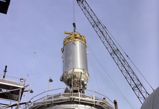
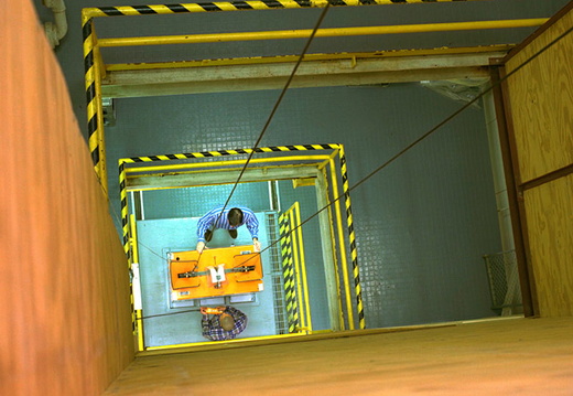
The NASA Glenn 2.2 Second Drop Tower is one of two drop towers located at the NASA site in Brook Park, Ohio. The tower, which began life as a 100-foot high fuel distillation tower, dangles over a bluff at the Glenn Research Center. The tower has been used forover 50 years by researchers from around the world to study the effects of microgravity on physical phenomena such as combustion and fluid dynamics, and to develop new technology for future space missions.
Microgravity, which is the condition of apparent (near) weightlessness, can only be achieved on or near Earth by putting an object in a state of free fall. In this way, NASA conducts microgravity experiments on Earth using drop towers and aircraft flying parabolic maneuvers, and in space using unmanned rockets, and the International Space Station.
The 2.2 Second Drop Tower is “a gateway to space” for many of the microgravity experiments conducted on the International Space Station because these experiments often begin on Earth with exploratory testing in the drop tower. This may be followed by further drop testing to verify or optimize the design of the space hardware and to identify the best test conditions for the space experiment. As such, the drop tower is used to maximize the scientific return from experiments conducted in space. This is an important role, given the significant investment required to conduct space experiments in both time and money.
The drop tower’s 2.2 second microgravity test time is created by allowing the experiment package to free fall a distance of 79 feet (24 m). The Drop Tower uses an experiment/drag shield system to minimize the aerodynamic drag on the free falling experiment. Experiments are assembled in a rectangular aluminum frame which is enclosed in an aerodynamically designed drag shield (which weighs 725 pounds, 330 kg). This package is hoisted to the top of the tower (the eighth floor), where it is connected to monitoring equipment (e.g., high-speed video cameras and on-board computers) before being dropped. A low gravity environment is created as the package freefalls from the eighth floor to the first floor, a distance of 79 feet 1 inch (24 m). The experiment is isolated from aerodynamic drag because it is not attached to the drag shield. The experiment itself falls seven and one half inches (19 cm) within the drag shield while the entire package is falling. The drop ends when the drag shield and experiment are stopped by an airbag, located at the bottom of the tower.
8×6 SUPERSONIC WIND TUNNEL
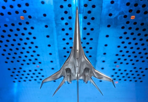
The 8×6 is a world-class facility that provides researchers with the opportunity to explore higher speed regions of flight. It is NASA’s only transonic propulsion wind tunnel. Actively involved in research testing for over 65 years, this facility has been used to enhance the nation’s aeronautics program serving industry, academia, and NASA in-house efforts. Aircraft such as the Advanced Turboprop, the National Aerospace Plane, and Advanced Tactical Fighter, the Joint Strike Fighter, and the High-Speed Civil Transport have been tested in this facility.
The test section of this facility is 8 feet high by 6 feet wide and 23.5 feet long. The flexible wall nozzle located upstream of the test section is constructed entirely of stainless steel and is used to accelerate the free-stream airflow when its walls are contoured to form a convergent divergent nozzle. To create the pressure required for the airflow to reach speeds up to Mach 2.0, a seven-stage motor-driven compressor located inside the tunnel loop is used. Surrounding the test section walls, a balance chamber is used to provide boundary layer control of the airflow in the test section through perforations in the test section walls. The tunnel can operate at speeds from 0 to Mach 0.1 and from Mach 0.26 to 2.0.
The facility operates either in an aerodynamic closed-loop cycle, testing aerodynamic performance models, or in a propulsion open-loop cycle that tests live fuel burning engines and models. In the propulsion cycle, the tunnel operates by continuously drawing outside air through an air dryer and exhausting it back into the outside environment after it exits an acoustic muffler. This cycle is critical for models that introduce contaminants into the air or use potentially explosive gas mixtures. No exhaust scoop is required in this cycle.
To maximize data quality and minimize operational costs, the facility is controlled and monitored by a digital distributed control system. Steady-state data is collected from model instrumentation, processed and displayed real-time in engineering and graphical formats at an update rate of once-per-second. Transient data with sampling rates of 2 MHz/sec and an optical instrumentation suite of capabilities are available. To increase test productivity, a test matrix sequencer automatically changes model variables by using a pre-programmed test matrix. Real time transfer and display of all test data and information can be provided to customer locations outside of NASA Glenn.
Model supports available in the facility include a ceiling and floor strut for both supersonic and transonic test sections and a wall mount for large or half-span models.
9×15 Low-Speed Wind Tunnel
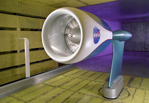
The 9×15 is a significant asset to the nation and the aero-propulsion community because of its unique ability to test large-scale hardware in a continuous subsonic air stream. With the ever-increasing demand for reducing aircraft noise, the importance of the 9×15 is greater than ever. Offering state-of-the-art acoustic capabilities, the facility is a vital part of the nation’s aeronautics research plans. Programs supported in this facility include a variety of commercial aircraft propulsion systems: the High Speed Civil Transport (HSCT), Advanced Tactical Fighter (ATF), Joint Strike Fighter (JSF) and other military short takeoff and vertical landing (STOVL) aircraft applications.
Built in 1968, the test section of the 9×15 is 9 ft high by 15 ft wide and 33 ft long. Providing airspeeds from 0 to 165 mph, this facility has unique and nationally recognized capabilities to evaluate aerodynamic performance and acoustic characteristics of nozzles, inlets and propellers.
The facility is acoustically treated and equipped with microphones linked to a dynamic data system. A series of drive rig systems are available to power engine fan models for performance and acoustic testing. A unique “rotor alone nacelle” test capability allows isolation of “fan alone noise” by elimination of outlet guide vanes.
10×10 SUPERSONIC WIND TUNNEL
The Unitary Plan Act, passed by Congress in 1949, was a coordinated national plan of facility construction that encompassed the National Advisory Committee for Aeronautics (NACA), Air Force, industry, and universities. In 1956, under the leadership of Dr. Abe Silverstein and Eugene Wasliewski, the 10×10 was brought on line. Dr. Silverstein was responsible for the Mercury program, and for all unmanned satellite programs for the first three years of the agency. He named the Apollo program and laid the groundwork for that program’s success in landing a man on the Moon.
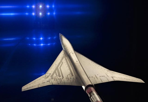
Throughout its history, the tunnel has made valuable contributions to the advancement of fundamental supersonic propulsion technology, the development of Atlas-Centaur, Saturn and Atlas-Agena class launch vehicles, and vehicle-focused research programs including the High-Speed Civil Transport, the National Aerospace Plane, and the Joint Strike Fighter.
The test section is 10 ft high by 10 ft wide by 40 ft long and can accommodate large-scale models, full-scale engines and aircraft components. The 10×10 was specifically designed to test supersonic propulsion components such as inlets and nozzles, propulsion system integration, and full-scale jet and rocket engines. It can operate as a closed-loop system (aerodynamic cycle) or open-loop system (propulsion cycle), reaching test section speeds of Mach 2.0 to 3.5 and very low speeds from 0 to Mach 0.36. Gust and Mach plates are sometimes installed to expand local Mach number conditions between Mach 1.5 and 4.1. There is also continuous operation across the entire speed and altitude regime, offering users greater flexibility and productivity during testing.
In the propulsion cycle, the tunnel operates by continuously drawing outside air through a very large air dryer to remove the moisture and exhausting it back into the outside environment. This mode is used for models that introduce contaminants into the air stream or use potentially explosive gas mixtures or when the tunnel air-heater is used to simulate flight temperatures. During the aerodynamic cycle, the tunnel runs as a variable density facility that can simulate pressure altitude conditions ranging from 50,000 to 154,000 feet. Dry air is added to maintain test conditions.
The facility is controlled and operated by a digital distributed control system in order to maximize data quality while minimizing operational costs. Steady state and dynamic data is collected from the model instrumentation, processed, and displayed in engineering units and graphical formats. An optical instrumentation suite of capabilities is also used depending on test requirements. To increase test productivity, a test matrix sequencer automatically changes model variables by using a pre-programmed test matrix. Real time transmission and display of all test data and information can be provided to customer locations outside of NASA Glenn.
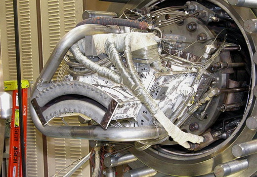
ADVANCED SUBSONIC COMBUSTION RIG
The Advanced Subsonic Combustion Rig (ASCR) at NASA’s Glenn Research Center (GRC) is a high-pressure, high-temperature combustion rig that simulates combustor inlet test conditions up to a pressure of 900 psig and temperatures up to 1300°F non-vitiated (no combustibles) at flow rates ranging from 5 to 50-lb/s. ASCR uses a dedicated high pressure compressor which pressurizes GRC’s centrally supplied 450 PSIG combustion air up to 900 PSIG, which is double the pressure capability of other combustor facilities at GRC. The maximum exhaust gas temperature from the test article is 3400°F.
The ASCR has been instrumental to NASA and its industry partners in developing low emissions combustor technology at higher operating pressures. Research has focused on developing low NOx combustors for pressure ratios up to 55:1. The ability of ASCR to operate up to 60 atmospheres provides a unique capability for NASA and engine manufacturers to quantify the effects of higher pressure on combustor emissions, durability and operability.
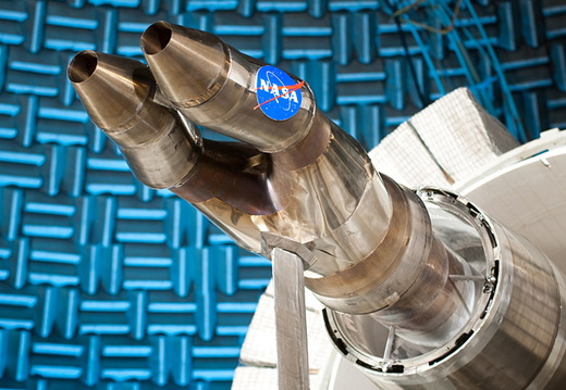
AERO-ACOUSTIC PROPULSION LABORATORY
With over 20 years of testing experience in acoustic research and development, the AAPL, located at NASA’s Glenn Research Center, is a world-class facility providing outstanding testing services in aircraft propulsion acoustic noise reduction and performance research.
Unique in testing capabilities and size, the AAPL dome is 65 ft high by 130 ft in diameter, providing an anechoic testing environment for engine component research and development. To provide a reflection free acoustic environment, 17,000 custom-designed 2‑ft thick fiberglass wedges are mounted on the dome’s interior walls and floor areas adjacent to the test rigs. The acoustically treated dome walls are designed specifically to attenuate sound. Together, these elements provide an acoustic testing environment that exceeds the acoustic research testing objectives set forth by NASA and industry.
AAPL houses three state-of-the-art acoustic test rigs, the Nozzle Acoustic Test Rig (NATR), Small Hot Jet Acoustic Rig (SHJAR), and the DGEN Aero-Propulsion Research Turbofan (DART).
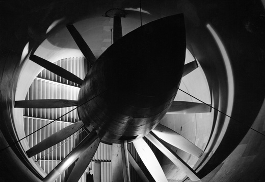
ALTITUDE WIND TUNNEL
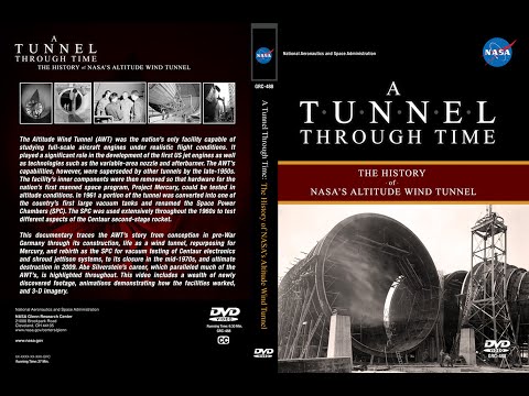
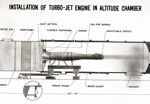
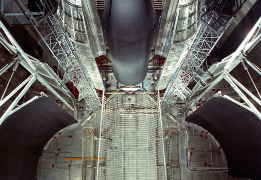
When constructed in the early 1940s, the Altitude Wind Tunnel (AWT) was the Nation’s only wind tunnel capable of studying full-scale engines under realistic flight conditions. It played a significant role in the development of the first U.S. jet engines as well as technologies such as the afterburner and variable-area nozzle. In the late 1950s, the center removed the tunnel’s interior components to test hardware for Project Mercury in altitude conditions. In 1961, the tunnel was converted into one of the country’s first large vacuum tanks to support the Centaur rocket program.
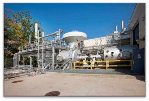
CHEMICAL PROPULSION RESEARCH COMPLEX
The Chemical Propulsion Research Complex (CPRC) develops advanced chemical propulsion concepts and evaluates safer propellants for launch vehicles, spacecraft thrusters and advanced ignition systems for next generation launch vehicles. It has the capability to perform sea level and simulated altitude testing, as well as advanced plume diagnostics. Workhorse hardware is available to perform component level testing. The testing facilities that comprise the research complex are highly configurable and able to meet varying customer needs. These facilities include the Altitude Combustion Stand (ACS), and CPRC cells 31 and 32.
COMBINED EFFECTS CHAMBER
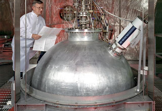
The Combined Effects Chamber (CEC) is a space-environment test chamber 25 ft in diameter with a 20 ft-diameter door. The design and construction of this facility allows large-scale liquid hydrogen (LH2) experiments to be conducted safely. Control and data systems are located in a separate, remote building and electrical control systems include explosion-proof hardware.
Other features of CEC include a removable LH2/LN2 cryogenic cold wall which can simulate deep space temperatures down to -423°F, vacuum-jacketed LH2 piping and chamber penetrations, a hydraulic shaker system, a vacuum-jacketed LH2 dump line and burnoff stack to handle accidental LH2 spills inside the chamber.
The CEC plays an essential role in the development of advanced insulation systems and on-orbit fluid transfer techniques for flight weight cryogenic fuel tanks and insulation systems.
The CEC is currently being considered for use as a Planetary Surface Simulation Test Facility, due to the chamber’s size and ease of access through the 20 foot hatch.
CREEK ROAD CRYOGENICS COMPLEX
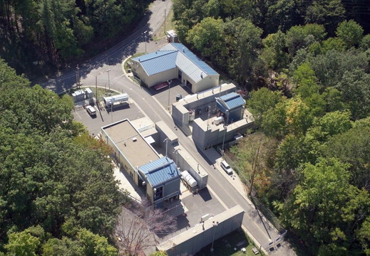
The Creek Road Cryogenics Complex (CRCC) is a state-of-art facility at NASA’s Glenn Research Center in Cleveland. It consists of four separate test cells: the Small Multi-purpose Research Facility (SMiRF), Cryogenics Components Lab 7 (CCL-7), Cryomotor Test Bed, and 20K to 90K Calorimeter Test Bed.
CYCLOTRON FACILITY
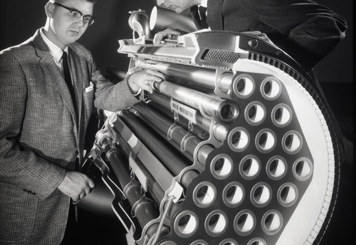
The Cyclotron Facility was built in the 1950s to study effects of radiation on materials for nuclear aircraft engines. The research expanded to general nuclear physics, the effect of solar radiation, and production of medical isotopes. In the 1970s and 1980s the Cleveland Clinic Foundation used the cyclotron to study the effect of fast neutrons on cancerous tumors.
ELECTRIC PROPULSION RESEARCH BUILDING
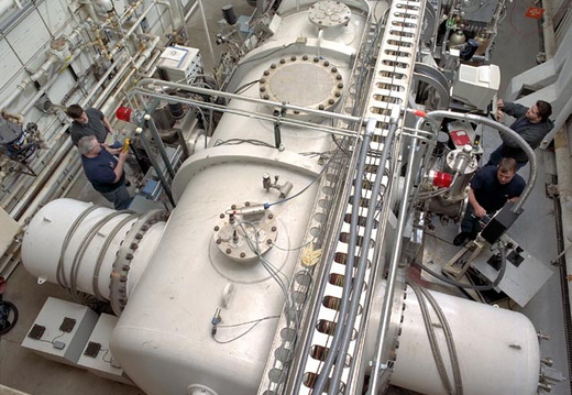
The Electric Propulsion Research Building (EPRB) supports research and development of spacecraft power, electric propulsion, and space environmental effects. Presently, EPRB is supporting research focused on ion thrusters, pulsed plasma thrusters, stirling engine converters, regenerative fuel cells, space plasma potentials, and atomic oxygen.
The cornerstone to EPRB’s research capabilities results from its suite of space simulation chambers. EPRB chambers range in size from bench top bell jars to 3-meters in diameter and are equipped with various pumping systems (cryopumps, diffusion pumps, oil-free pumping trains, and high-throughput roots-blowers) depending upon the specific requirements of a test program. In addition, EPRB has over 20,000 square feet of specialty labs, build-up area and machine shop area. EPRB works synergistically with other larger vacuum facilities located at GRC.
Research that is initiated in EPRB on a concept or component level leads to a system or higher fidelity tests in facilities such as VF-5 (very high pumping speed), VF-6 (unique in its electric propulsion features), or SPF (world’s largest vacuum chamber). This insures that these world-class facilities are effectively utilized and that research is done in the most cost-effective manner possible.
EPRB has eight vacuum chambers and five bell jars that provide the required simulated space to conduct fundamental research in space power and electric propulsion. These vacuum facilities are further enhanced to insure GRC continues to provide the technology development necessary for NASA to explore the solar system.
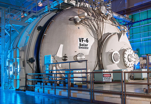
ELECTRIC PROPULSION AND POWER LABORATORY
The Electric Propulsion and Power Laboratory (EPPL), formerly known as the Electric Propulsion Laboratory (EPL), supports research and development of spacecraft power and electric propulsion systems.
EPPL features two very large space environment simulation chambers; intermediate and smaller environment simulation chambers suitable for testing small engines or components; bell jars used for development and small-scale component testing; and support areas including an electronics shop, machine shop, clean room, and office space.
The space simulation chambers have been enhanced to support the unique requirements of electric propulsion and power system testing. VF-5 cryopumps 3.5 million liters of air per second with its 33.5 sq meter of 6 K helium cryopanels. Several of the chambers have multiple air-locked access ports. These ports allow several tests to be conducted simultaneously in each chamber without cycling the chamber back to atmospheric pressure during introduction or removal of test hardware. Conditioned DC power is supplied to VF-5, VF-6 and VF-12 for powering ion, hall and MPD thrusters.
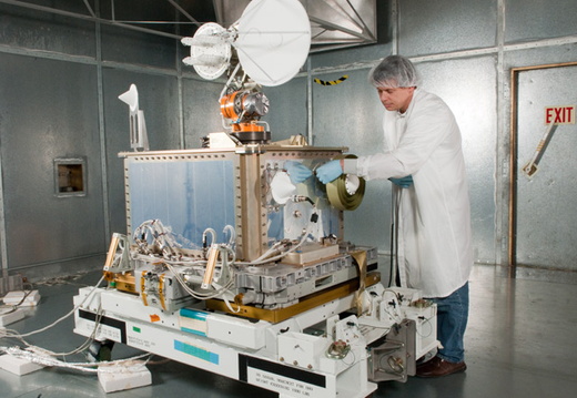
Fission Surface Power Technology Demonstration Unit.
The staff of EPPL have been supporting electric propulsion and power system testing for over 40 years and have developed technology leading techniques with precision thrust balances, thruster erosion diagnostics, plume characterization, and EMI/EMC.
ELECTROMAGNETIC INTERFERENCE LABORATORY
The Electromagnetic Interference (EMI) Laboratory offers several Electromagnetic Compatibility (EMC) services like EMC hardware design to meet the desired requirement, specification comparisons, consultation during design development, and prefabrication analyses. The EMI Lab provides intermediate testing as the design progresses, testing for shielding effectiveness, filtering, and grounding, final qualification testing of experiments in flight configuration, and testing at customer locations for items too large to fit in the EMI Laboratory shielded room.
This facility consists of three shielded rooms, two test chambers, and a control room. All walls, ceiling, and floors are constructed of 26-gauge galvanized steel sheets laminated to both sides of a structure core.
The rooms meet the electromagnetic wave attenuation requirements used by the National Security Agency (NSA). They prevent transmission of electromagnetic waves into, or out of, the enclosure, which provides low electric and magnetic field ambient conditions. Electrical power is provided through filtered AC lines to eliminate transfer of interfering signals such as radio, TV, and RADAR.
The large shielded enclosure is a fully functional package with support for stirred and tuned mode operation with Statistical Mode Averaged Reverberation test. This methodology of test is good for Immunity test or Shielding Effectiveness test.
ELECTROMOTIVE DROP TOWER INITIATIVE
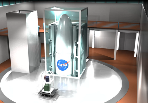
The Electro-Motive Drop Tower (EMDT) is a proposed upgrade to the existing Zero Gravity Research Facility (ZGF) – NASA GRC’s 5.2-second drop tower. The initiative aims to improve the ZGF; increasing test throughput, low gravity duration, and providing intermediate gravity levels, such as lunar and Martian gravity. The concept is similar to what has been built at Leibniz University in Hannover Germany. The feasibility of constructing an Electro-Motive Drop Tower in the ZGF shaft has been studied extensively during the past few years. The rail guided, linear motor driven EMDT concept shows promise for nearly doubling the facility test time, increasing facility test throughput by an order of magnitude, and offering the possibility of performing tests in alternate gravity levels; all important to advancing NASA’s mission.
ENGINE RESEARCH BUILDING
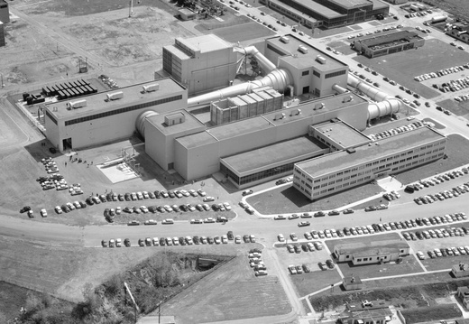
The Engine Research Building (ERB) is the largest and most adaptable test facility complex at Glenn, with 152,235 square feet of floor space housing more than 60 test rigs. Most aspects of engine development can be studied here with numerous facilities specializing in turbomachinery, tribology, flow physics, combustion, aerochemistry, mechanical components, and heat transfer.
Fundamental and applied research is conducted in the following test facilities:
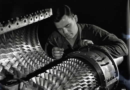
Compressor and turbine research is conducted in the turbomachinery facilities to advance new technology for components of aeronautical gas turbine engines. Glenn Research Center is NASA’s Center of Excellence in turbomachinery.
Advanced lubricants, oil-free bearings and other components are tested in the tribology facilities to develop clean, fuel-efficient engine technologies requiring less maintenance.
Work to develop and validate computational fluid flow codes, and the subsonic to supersonic flow physics phenomena fundamental to ducted wall-bound flows is conducted in the aerodynamic flow physics.
The combustion processes of aeronautical gas turbine engines, including chemical reactions and combustion flow physics to develop gas turbine combustor technology, is conducted the combustion and aerochemistry.
Components for gas turbine engines, rotorcraft, space propulsion, and space mechanisms are developed in the mechanical components.
Gas path heat transfer with an emphasis on advanced materials is explored in the aeropropulsion heat transfer facilities.
HYPERSONIC TUNNEL FACILITY
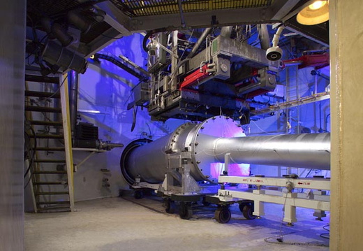
Designed to conduct research, development, and acceptance testing of hypersonic airbreathing propulsion systems, the Hypersonic Tunnel Facility (HTF) is a fully self-contained facility. Its experimental infrastructure includes a shop area for fabrication of materials for facility subsystems and assembly of customer hardware. Due to the high-energy nature of the facility, it is operated remotely from a control room approximately one-quarter mile from the actual facility.
The HTF is a blow-down, non-vitiated, free jet wind tunnel that is capable of simulating Mach 5, Mach 6, and Mach 7 true enthalpy conditions. The primary performance differentiator between the HTF and other hypersonic free jet facilities is its non-vitiated (clean) flow. Whereas traditional facilities of this type utilize a combustion process to generate high enthalpy conditions required to simulate hypersonic flows, the HTF generates these conditions by flowing nitrogen gas through a 3 MW graphite core storage heater. This heated nitrogen is then mixed with ambient temperature oxygen and ambient temperature nitrogen to yield a flow of synthetic (true composition) air at the requisite stagnation temperature. Three interchangeable nozzles are used to establish the facility Mach number condition of 5, 6, and 7. A nominal free jet test section ‘characteristic dimension’ is the nozzle exit diameter, 42 inches for the HTF.
However, the hypersonic core flow varies with Mach number. The test section length can be adjusted from 10 feet to 14 feet in length. Utilization of aeroappliances around test hardware is standard practice. A single stage steam ejector is used to exhaust the facility flow and provide altitude simulation.
The facility’s size and long run duration allow for full systems testing of large flight rated structures and propulsion systems. The facility is capable of supporting both hydrogen and hydrocarbon fueled propulsion systems. In addition to free jet testing, the use of the facility to support direct connect subsonic and supersonic combustion is currently being developed. This capability would allow for the testing of large scale combustors in a non-vitiated flow.
ICING RESEARCH TUNNEL
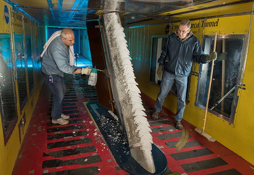
The Icing Research Tunnel (IRT) is the longest running, icing facility in the world and has been in operation since 1944. Most ice protection technologies in use today were largely developed at this facility. In this facility, natural icing conditions are produced to test the effects of icing conditions on aircraft components such as wings tails and engine inlets.
A variety of tests are performed in the IRT including fundamental studies of icing physics, icing prediction validation, and ice protection system development and certification. These tests have been used successfully to reduce flight test hours for ice detection instrumentation and ice protection systems certification.
The IRT can produce airspeeds from 50 to 325 knots and temperatures as low as -35°C year-round, controllable to within 0.5 degree Celsius. Supercooled water droplets between 15 and275 microns with water content between 0.15 and 4.0 g/m3 can be produced to form an icing cloud. The 6 feet high, 9 feet wide, 20 feet long test section can accommodate many full-sized aircraft components as well as large-scale models and an 8.6 ft diameter turntable in the test section can rotate horizontally +/-20 degrees for various angles of attack for various angles of attack.
IN-SPACE PROPULSION FACILITY
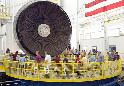
NASA’s In-Space Propulsion Facility (ISP), formerly known as the Spacecraft Propulsion Research Facility (B–2), is the world’s only facility capable of testing full-scale upper-stage launch vehicles and rocket engines under simulated space conditions and also conducting altitude hot fire. The engine or vehicle can be exposed for indefinite periods to low ambient pressures, low-background temperatures, and dynamic solar heating, simulating the environment the hardware will encounter during orbital or interplanetary travel.
MICROSYSTEMS FABRICATION LABORATORY
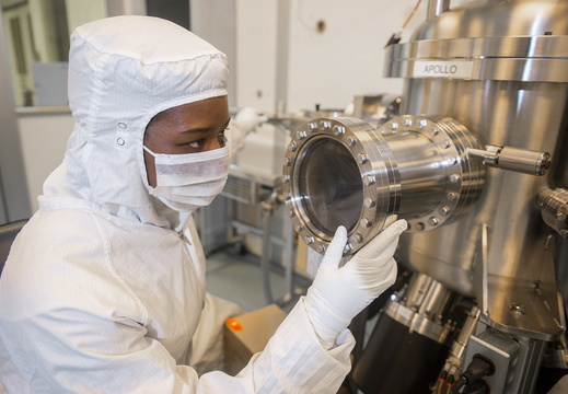
The NASA Glenn Microsystems Fabrication Laboratory (MFL, located in Building 77) is a vertically integrated silicon carbide (SiC) semiconductor research and development facility dedicated to design, fabrication, and testing integrated circuit electronics and sensors uniquely durable to extreme environments. To date MFL is the only laboratory in the world that has fabricated and tested packaged semiconductor integrated circuits operating at 500 °C for over a year. This laboratory is available for assisting external partners in the design and prototyping of developmental extreme environment SiC sensors and electronics under mutual agreement negotiated by the NASA Glenn Technology Transfer Office
PLANETARY EXPLORATION TEST FACILITIES
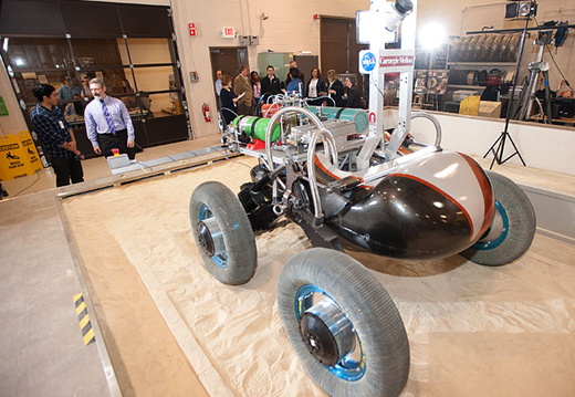
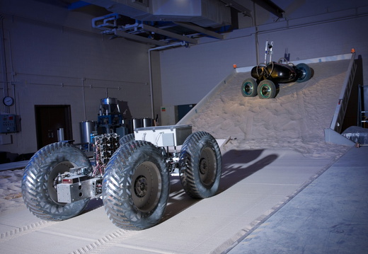
There are several state-of-the-art test rigs and facilities at the NASA Glenn Research Center (GRC) operated by GRC’s mTRAX Planetary Exploration team. Most of the facilities are located in the Engine Research Building (ERB). These rigs serve to test planetary roving vehicle systems and components in simulated planetary and lunar conditions. Most of the test capabilities are focused on the interactions between rover components (such as tires and excavation tools) and the terrain, though there are environmental test capabilities as well. A few examples of ongoing research in these labs includes conducting full-scale vehicle mobility tests to determine new methods for traversing challenging terrain, evaluating the performance of novel rover tires in lunar and Martian environments, and testing various excavation techniques for digging on the Moon.
POWER SYSTEMS FACILITY
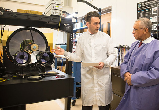
The Power Systems Facility (PSF) was initially constructed in the 1980s to test space station hardware. Over thirty years later, the facility remains the focal point of power systems research and provides the capability for remote operation of space station experiments from NASA Glenn Research Center (GRC). For more history of the PSF, see how Glenn’s Power System Facility Has Supported Station Research for Decades.
The PSF houses testbeds where scientists and engineers verify critical design concepts, test prototype hardware and software, and validate systems in real-time simulations under actual loading and operating conditions.
The PSF offers the capability for test and development of spacecraft power sources, spacecraft communication systems, and power management and distribution hardware and software. The PSF provides an exceptional platform to not only test and verify today’s space power systems, but also to design, develop, and test components and systems for new technologies.
The facility serves many purposes ranging from aeronautics and space power systems technology development in the ambient laboratories to qualification and acceptance testing of spaceflight hardware in the high bay cleanroom. The PSF is also home to the Glenn Research Center (GRC) International Space Station (ISS) Payload Operations Center (GIPOC) , formerly called the Telescience Support Center (TSC) for on-orbit operations of space experiments.
Recent examples of projects that have benefitted from PSF include the Orion Project, which through the build-up and testing of an Orion capsule and service module power system, key decisions were made on the spacecraft bus voltage. Additionally, the PSF is home to the Radioisotope Stirling Integration Laboratory (RSIL), which was constructed to verify and validate the avionics and control for a Stirling power conversion system, used in conjunction with a radioisotope source for deep space unmanned missions. Enabling a capability for hardware and software integration, the Modular Power Testbed and the Autonomous Power Control Lab are able to demonstrate critical technology for human missions to Mars and perform cross-center tests of the simulations and control algorithms with the NASA Ames Research Center and the NASA Johnson Space Center through the Space Network Research Federation (SNRF).
The PSF is a hidden gem at GRC as it is home to a breadth and depth of power systems testing, ranging from low Technical Readiness Level (TRL) research and proof-of-concept, to mid-TRL technology maturation, all the way through flight and operations within the high bay and TSC. Over the years, PSF has provided support to all of NASA’s mission directorates, including the development of power technologies for the Revolutionary Vertical Lift Technology (RVLT) Project and the assembly of Spacecraft Fire Safety (SAFFIRE) experiments in the high bay. An adjacent solar array field provides 960 solar cell modules to power system hardware during testing. Today, PSF continues to build upon its legacy that began with space station power system, infusing new technologies and ideas into projects and programs and leveraging its highly skilled and experienced workforce at NASA GRC
PROPULSION SYSTEMS LABORATORY NO. 1 AND 2
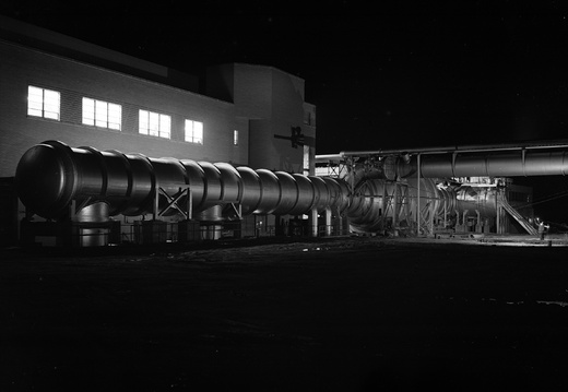
The Propulsion Systems Laboratory (PSL) complex provides world-class test and evaluation capabilities in support of NASA’s research and testing mission and charter. Built in the early 1970s, PSL has hosted a number of unique programs that have furthered engine research technologies.
Altitudes to 90,000 ft and Mach numbers to 3.0 in one cell and 6.0 in the other can be simulated continuously. Engine airflow is available to 480 lb/s at an inlet pressure of 55 psia or to 380 lb/s at 165 psia. Inlet temperature control is also available. Real-time display and post-test data reduction are available for all measured and calculated parameters.
The PSL is a highly versatile test facility developed to suit the one-of-a-kind testing common to NASA aeronautics research and testing programs. This versatility allows quick reaction to changes in program direction, as well as complete flexibility to pursue new goals that arise unexpectedly from ongoing experimental research.
Unique concepts in altitude engine testing have been pioneered and perfected in the PSL, such as multiaxis thrust measurement, vectored and reverse exhaust gas collection, infrared imaging at altitude, aeroelastic measurements, transient pressure and/or temperature distortion simulation, and flight transient simulation. Recognizing innovation, other test organizations have asked to share PSL’s expertise.
RESEARCH SUPPORT BUILDING
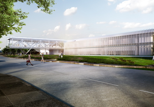
RSB will be a 64,000-square-foot multi use office building providing office space for approximately 160 permanent occupants. The building will also be home to the cafeteria, hoteling spaces, exchange store, ATM, training rooms and conference rooms. The RSB is designed with collaboration in mind, including multiple break out spaces throughout the building, low partition workstations, and specialized concurrent engineering rooms.
The RSB will sit adjacent to the Mission Integration Center (MIC). These two buildings are key to creating a Campus Center at Lewis Field, a central destination envisioned to promote innovation and serve as a campus center and gathering location for the Glenn community.
The RSB takes an integrative approach to sustainability, workplace evolution, and maintainability. Design and construction of the building operations are focused to meet modern day building energy performance requirements while achieving a minimum LEED Silver certification.
The area between the RSB and MIC will be transformed into a campus commons to accommodate outdoor events. The RSB signature architecture is intended to promote the campus center, inviting staff and visitors alike. The construction contract for the new two-story building was awarded in August 2018, with site construction anticipated to begin in fall 2018.Full occupancy is expected in the fall of 2020
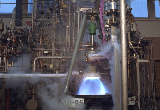
ROCKET ENGINE TEST FACILITY
The Rocket Engine Test Facility (RETF) was a National Historic Landmark located at the NASA Glenn from 1957 to 2003. The facility played an integral part in the development of high-energy liquid propellants. Testing of subscale rocket engines in RETF expanded understanding of combustion and led to new designs. RETF made valuable contributions to Pratt & Whitney’s RL–10 engine and Rocketdyne’s F–1 and J–2 engines.
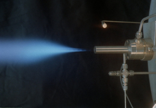
ROCKET LABORATORY
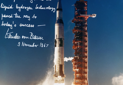
The Rocket Laboratory at the NASA Glenn Research Center was critical to the development of high-energy liquid propellants such as liquid hydrogen in the 1940s and 1950s. The facility’s once-rudimentary equipment was subsequently replaced with advanced technologies. The versatile suite of test cells has since tested an array of thrusters, combustors and alternative fuels.
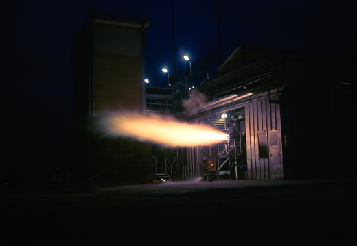
ROCKETS SYSTEMS AREA
In the 1960s NASA Glenn Research Center’s remote testing facility at Plum Brook Station in Sandusky, Ohio, was an essential element in the development of liquid-hydrogen propulsion systems for rocket engines. At its peak, Plum Brook contained 15 different facilities with at least 24 test rigs and cells that tested turbopumps, engine components, and propellant tanks for these hydrogen-powered rocket systems.
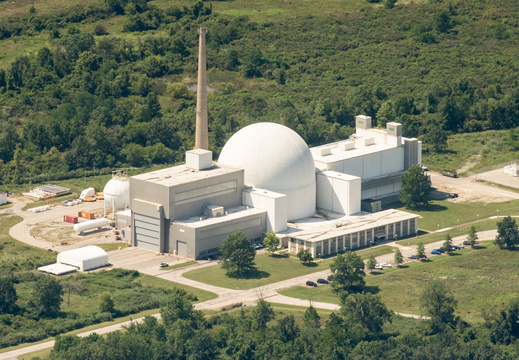
SPACE ENVIRONMENTS COMPLEX
The Space Environments Complex (SEC) houses the world’s largest and most powerful space environment simulation facilities. The Space Simulation Vacuum Chamber is the world’s largest space simulation vacuum and EMI chamber, measuring 30.5 m (100 ft) in diameter by 37.2 m (122 ft) high. The Reverberant Acoustic Test Facility (RATF) is the world’s most powerful spacecraft acoustic test chamber, and the Mechanical Vibration Facility (MVF) is the world’s highest capacity and most powerful spacecraft shaker system. The SEC is located at the NASA’s Neil A. Armstrong Test Facility (ATF) in Sandusky, Ohio. This website provides information on the capabilities of this facility and the supporting infrastructure. The facility is available on a full-cost reimbursable basis to government, universities and the private sector.
SPECIAL PROJECTS LABORATORY
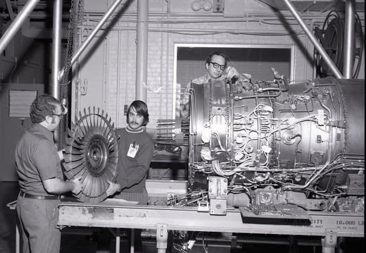
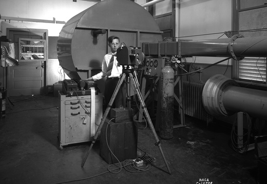
The Special Projects Laboratory (SPL) at the NASA Glenn Research Center played an important role in the center’s aeropropulsion research for over 70 years. The facility, which was named the Jet Propulsion Static Laboratory (JPSL) from 1944 to 1961, made significant contributions to the center’s propulsion and materials research before being removed in 2018.
STRUCTURAL DYNAMICS LABORATORY
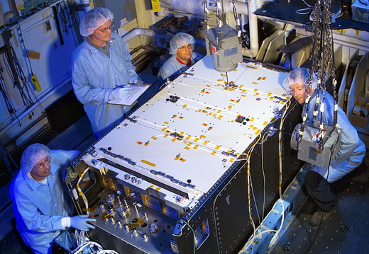
The Structural Dynamics Laboratory, or SDL, performs tests to verify the survivability of a component or assembly when exposed to vibration stress screening or a controlled simulation of the actual flight or service vibration environment.
Environmental stress screening, or workmanship vibration, is used to identify latent manufacturing defects of components before they are incorporated into larger assemblies. Vibration testing is also used to verify design margins of assemblies and to characterize the internal dynamic responses of a test article.
The Microgravity Emissions Laboratory (MEL), is a part of the Structural Dynamics Laboratory which provides testing support for simulation and verification of the Space Station microgravity environment. Together, the labs combine environmental, modal, and characterization work in one facility.
STRUCTURAL STATIC LABORATORY
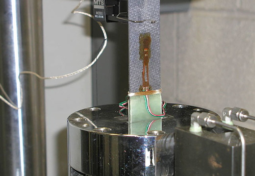
Structural testing is performed to verify the structural integrity of space flight and ground test hardware. Testing is also performed to verify the finite element analysis by measuring stiffness and induced stress at points in a test article. A structural test can be used to verify the modes of failure of a design when exposed to simulated service loads.
The modes of failure include but are not limited to the following: leak before burst, buckling, ultimate failure, yield or excessive deflection. The test lab is also outfitted with a tensile test machine that can be used to develop mechanical properties, at up to 1300°F, in metallic coupons, composite coupons, adhesive joints, and weld joints. A high-temperature laser extensometer can be used to give accurate strain data during tensile testing at elevated temperatures.
ZERO GRAVITY RESEARCH FACILITY
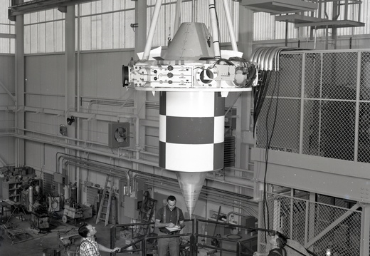
The Zero Gravity Research Facility is NASA’s premier facility for ground based microgravity research, and the largest facility of its kind in the world. The Zero-G facility is one of two drop towers located at the NASA site in Brook Park, Ohio. The Zero-G facility has been operational since 1966. It was originally designed and built during the space race era of the 1960s to support research and development of space flight components and fluid systems, in a weightless or microgravity environment. The facility is currently used by NASA funded researchers from around the world to study the effects of microgravity on physical phenomena such as combustion and fluid physics, to develop and demonstrate new technology for future space missions, and to develop and test experiment hardware designed for flight aboard the International Space Station or future spacecraft.
The Zero-G facility provides researchers with a near weightless or microgravity environment for a duration of 5.18 seconds. Microgravity, which is the condition of relative near weightlessness, can only be achieved on Earth by putting an object in a state of free fall. NASA conducts microgravity experiments on earth using drops towers and aircraft flying parabolic trajectories. Allowing the experiment hardware to free fall a distance of 432 feet (132 m) creates the microgravity environment at the Zero-G facility.
The free fall is conducted inside of a 467 foot (142 m) long steel vacuum chamber. The chamber is 20 ft (6.1 m) in diameter and resides inside of a 28.5 ft (8.7 m) diameter concrete lined shaft, which extends 510 feet (155 m) below ground level. A 5 stage vacuum pumping process is used to reduce the pressure in the chamber to a pressure of 0.05 torr (760 torr = standard atmospheric pressure). Evacuating the chamber to this pressure reduces the aerodynamic drag on the freely falling experiment vehicle to less than 0.00001 g. To prepare for a drop, an overhead crane is used to position the experiment vehicle and release mechanism at the top of the vacuum chamber. Once in position, the drop vehicle is connected to the facility control room via an umbilical cable. This cable allows the experiment to be monitored and controlled from the control room until the release sequence is initialized. It takes approximately one hour to evacuate the vacuum chamber. Once the chamber is evacuated the release sequence is initiated. Remotely fracturing a specially designed bolt allows the experiment to begin its 132 meter free fall. During the drop the experiment operates autonomously with all experiment power, data acquisition, and control functions located on the freely falling experiment vehicle.
After falling for just over 5 seconds the experiment vehicle is stopped in the decelerator cart, located at the bottom of the chamber. The decelerator cart is 11 foot ( 3.3 m) in diameter and nearly 20 ft (6.1 m) deep. It is filled with 1/8” (3 mm) diameter expanded polystyrene beads. These beads dissipate the kinetic energy of the 2500 lb. experiment vehicle, which is traveling at about 113 mph (50.5 m/s) when it enters the decelerator cart. The experiment vehicle is stopped in about 15 feet (4.6 m) of expanded polystyrene and experiences a peak deceleration rate approaching 65g.
The experiment drop vehicle serves as a load bearing structure and protects the experiment hardware from the shock loads experienced during the deceleration. The typical drop vehicle used is cylindrical in shape. It is 42” in (1 m) diameter and has and overall length of 13 ft (4.0 m). The drop vehicle gross weight is limited to a maximum of 2500 lbs (1130 kg).
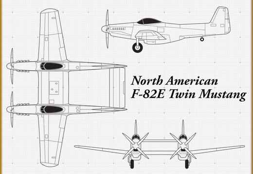
AIRCRAFT GALLERY
This page highlights some of the research aircraft used by the National Advisory Committee for Aeronautics’ (NACA) Aircraft Engine Research Laboratory (AERL)1 in Cleveland, Ohio. Congress established the NACA in 1915 to coordinate the nation’s aeronautical research. The committee established the Langley Memorial Aeronautical Laboratory in 1917 to conduct research of its own. From the beginning the use of aircraft was a critical element to the NACA’s efforts. The first test flights took place in 1918, two years before Langley was completed, and continued until the organization was incorporated into the National Aeronautics and Space Administration (NASA) on October 1, 1958.
In response to European aviation advances in the late 1930s, the NACA created two new research laboratories which dramatically expanded its capabilities. Construction of the Ames Aeronautical Laboratory in Sunnyvale, California, and the AERL commenced in 1940 and 1941, respectively. The new laboratories relied on flight research to augment and verify their findings from wind tunnels and other ground-based test facilities.
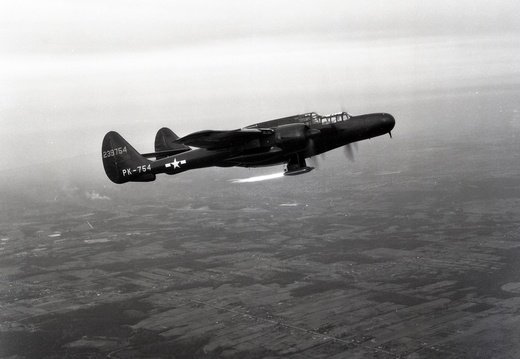
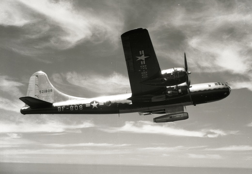
During World War II the military asked the NACA to resolve operating problems with existing piston-engine aircraft. The military supplied the AERL with a steady stream of aircraft to address issues regarding the engines and ice prevention. During the war, the aircraft were the same types for which the particular research was intended to benefit. For example, new methods of cooling the Wright R-2800 engines were verified with test flights on the R-2800-powered Martin B-26. After the war the NACA returned to advanced research and its aircraft served as test beds to investigate engines or systems that often had little to do with that particular aircraft. For instance a B-29 was modified so that a ramjet engine could be lowered from its bomb bay and fired during flight. The AERL possessed nearly 40 different aircraft during the NACA period, some only for months, others for many years. The history, NACA utilization, and specifications for eleven of these vehicles are highlighted below.
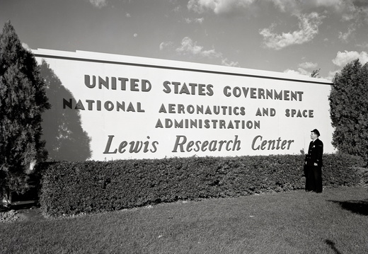
1 The Cleveland laboratory, now known as NASA Glenn Research Center, began operation in 1942 as the NACA Aircraft Engine Research Laboratory (AERL). In 1947 it was renamed the NACA Flight Propulsion Laboratory to reflect the expansion of the research. In September 1948, following the death of the NACA’s Director of Aeronautics, George Lewis, the name was changed to the NACA Lewis Flight Propulsion Laboratory. On October 1, 1958, the lab was incorporated into the new NASA space agency, and it was renamed the NASA Lewis Research Center. Following John Glenn’s flight on the space shuttle, the center name was changed again on March 1, 1999 to the NASA Glenn Research Center.
The selections below represent a list of some of the aircraft used to perform research and tests in support of the NACA's mission to enhance and improve aircraft performance and reliability. Select the "View Info" button below any of the images to learn more about a specific aircraft.
MITIGATION WORK
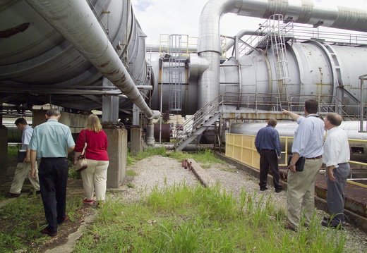
The NASA Glenn Historic Preservation Office has worked with the Ohio State Historic Preservation Office and Glenn History Office to develop strategies, budgets, and work plans to record the history of these facilities. These projects consists of two facets—the documentation and preservation of the facility’s history and the interpretation and dissemination of that information to the public.
The documentation included the collection of documents and audio/visual materials from the Glenn Records holdings, the Glenn History Office archives, retirees, the NASA Technical Reports Server, newspaper databases, and other sources. It also includes the scanning of negatives, conducting interviews with former employees, and performing photographic surveys of the sites prior to their demolition.
The collected information is distilled into a variety of different products that are made available to the public and NASA staff. These have included books, documentary videos, websites, exhibits, interactive media, and Historic American Engineering Reports.
These efforts strive to create a permanent documentary record for the facility, offer lessons learned for the agency, increase public awareness of NASA Glenn contributions to society, and provide a collected body of materials for future researchers.
In accordance with the National Preservation Act, the center has also held community awareness meetings before each demolition. The attendees learn details about the proposed demolitions, the history of the facilities, efforts underway to document the facilities, and the results of the environmental impact studies conducted for the projects. The meetings give the attendees the opportunity to ask questions and voice any opposition to the projects.
